


Next: About this document ...
Chapter 20
Electric Currents
So far, we have dealt with an abstract definition of voltage, i.e. the (potential) energy
that a unit charge has because of being in a region of electric field. But what does
this have to do with you going to the hardware store and buying, e.g., a 6 V battery?
Well, we can use our knowledge to state that this means that a unit positive charge
at the + terminal of the battery has 6 joules more (electric potential) energy than if it was
at the negative terminal (or, in general, a charge  has
has  J more energy at the
positive than at the negative terminal). Alternatively, you might say that if this charge q was
allowed to go from the positive to the negative terminal, somehow joules of energy
(initially in the form of potential energy) would be available to be transformed into another energy
form. Example :
J more energy at the
positive than at the negative terminal). Alternatively, you might say that if this charge q was
allowed to go from the positive to the negative terminal, somehow joules of energy
(initially in the form of potential energy) would be available to be transformed into another energy
form. Example :
when you connect the terminals of a battery to a light bulb, a certain amount of charge goes
through the bulb filament, and, in doing so, produces a certain amount of light and heat, and
we know that light and heat are both forms of energy). If we were able to measure the various
quantities involved, we would see that the energy produced as light and heat was in fact
equal to the product of voltage times charge transited through the filament.
(Incidentally: in a battery a voltage difference is maintained at the terminals by the effect of
chemical reactions onto two different metals, with the end result of one terminal being more
positively charged than the other. You can make a very simple battery by sticking two spikes of
different metals into a grapefruit...).
When the two terminals of a battery are kept separate, nothing happens, but if you connect
them through a conductor, excess negative charges (i.e. electrons) present at the negative
terminal will tend to migrate away from it towards the positive terminal. This flow of charges
through the conductor is what we call an electric current.
Note : in practically all cases of electric currents, it is the negative charges, i.e.
the electrons, that move through the conductor, going from regions of lower to higher voltages.
But, for historical reasons, the usual convention is to consider the electric current as flowing
from higher to lower voltages, i.e. in direction opposite to that of the electrons.
Another unfortunate historical convention is that the potential difference present, e.g., at a
battery's terminal is called electromotive force, even though we know very well that a
potential is not a force, it is an energy per unit charge.
In quantitative terms, we define as current through a conductor the amount of charge going
through a cross section of the conductor per unit time
I = q/t
and we measure it in amperes, 1 ampere = 1 coulomb/1 sec. Remembering that the coulomb
is a rather large amount of charge we can guess that 1 A is a rather large current.
It is often useful, up to a certain extent, to think of electric currents in terms of water
flowing through some conduit. Here is then how we can interpret the simple circuit of a battery
connected to a light bulb through some wires :
- the same way that a pump can lift some water to a higher level, giving it some
(gravitational) potential energy, so the battery gives some potential energy to the charges
- connecting wires are like water pipes or conduits. To a good approximation, we can neglect
any energy loss as the fluid (charge) flows through the conduits (wires), (for a fluid this would
be the case of negligible viscosity)
- the water's potential energy can be used, e.g., to turn the wheel of a mill. In doing so
the water transfers its energy to the wheel, and to get more work out of it we have to lift it
again with the pump. Similarly, charges will dissipate their energy to produce heat and light.
After they go through the light bulb, the charges are back down to zero potential.
Question: we have said a few times that when energy is transferred from one form (or body) to
another some work is involved. In the case of a bulb being lit, who is doing the work?
Let us now discuss the relation between current and voltage in a more quantitative fashion. When a
conductor is used to join two points that are at different
potential (=different voltage), then a current, i.e. a certain amount of charge per unit time,
will flow. Question : how much current will flow for a given potential difference ?
The answer is that, under most conditions of interest to us, the current is proportional
to the voltage difference, the exact value depending upon the properties of the conductor.
We express this by means of Ohm's Law
I = V/R
where R is the resistance of the conductor, i.e. a quantity that describes how much the
conductor opposes the passage of the current. Obviously, for a given voltage, the lower the
resistance the higher the current, and viceversa. Resistances, which are measured in
ohm's (1 ohm=1 volt/1 ampere,  = V/A) depend on the type of material as well as on the
geometry of the conductor, according to
where L is the conductor's length, A the cross-section and
= V/A) depend on the type of material as well as on the
geometry of the conductor, according to
where L is the conductor's length, A the cross-section and  is the resistivity,
a quantity characteristic of the material. The resistivity is not exactly a constant, since,
for most ordinary conductors, it increases with increasing temperature.
is the resistivity,
a quantity characteristic of the material. The resistivity is not exactly a constant, since,
for most ordinary conductors, it increases with increasing temperature.
At extremely low temperatures, near the absolute zero, many conductors exhibit an intriguing
and important behaviour, called superconductivity, whereby any resistance to the
flow of current effectively vanishes. Superconductivity (whose theoretical explanation can only
be done within the realm of Quantum Mechanics) is being actively investigated, since it could
lead to extremly efficient utilization of electric energy. Unfortunately, applications are not
yet practical, since they require temperature close to absolute zero.In a very recent breakthrough,
special ceramics were shown to become superconductive at "warm" temperatures ( around 150 K) which
are above the temperature of liquid nitrogen. Given that nitrogen can be liquified with relative
ease, there is great promise for widespread applications of superconductivity.
Electric Power
Power, as we remember, is energy per unit time , P= E/t . But electric energy is voltage times
charge, E = V q, therefore
P = E/t = Vq/t = VI
If you ever wondered what does it mean to have a 100 watt light bulb, now you know the answer:
when connected to the 120 V electric supply, it will allow a flow of 100/120  .83
amperes. And, by Ohm's Law, we can also infer that its resistance, when burning steadily, is
R = V/I = 120/.83 . If we keep our 100 W bulb burning for an hour, the total
(electric) energy it will consume is E = P x t = 100 x 3600 = 360000 J.
Electric energy is more often measured in kilowatthours (1 kWh = energy used when running at the
power of 1 kilowatt for an hour). How many kWh is the 100 W bulb then consuming in an hour ?
.83
amperes. And, by Ohm's Law, we can also infer that its resistance, when burning steadily, is
R = V/I = 120/.83 . If we keep our 100 W bulb burning for an hour, the total
(electric) energy it will consume is E = P x t = 100 x 3600 = 360000 J.
Electric energy is more often measured in kilowatthours (1 kWh = energy used when running at the
power of 1 kilowatt for an hour). How many kWh is the 100 W bulb then consuming in an hour ?
When combining the expression P =VI with Ohm's Law we can get two apparently contradictory
results :
, or
how can the power be simultaneously proportional and inversely proportional to the resistance?
To find our way out of this quandary, we must remember that, for a given voltage, an increase
in resistance will cause a decrease in current. Therefore, even though  , increasing
R, for a given voltage, will cause I to decrease (and
, increasing
R, for a given voltage, will cause I to decrease (and  will decrease even faster), so that,
in reality, a larger resistance will in fact correspond to a lower power being dissipated.
(but be aware that this is not the end of the story, the conclusion we just reached would
contradict Conceptual Example 7, where you are told that you should use lower-resistance
extension cords to prevent them from over-heating. We will understand how to solve this apparent
contradiction after we learn about resistances in series).
will decrease even faster), so that,
in reality, a larger resistance will in fact correspond to a lower power being dissipated.
(but be aware that this is not the end of the story, the conclusion we just reached would
contradict Conceptual Example 7, where you are told that you should use lower-resistance
extension cords to prevent them from over-heating. We will understand how to solve this apparent
contradiction after we learn about resistances in series).
Conceptual qyestions 5, (6, 7)
Problem : your water heater is connected to a 20 A circuit breaker. What is the smallest acceptable
value for the resistance of the heating element?
Alternating Currents
So far we have talked in terms of constant electric voltages provided by batteries and the
consequent steady currents (usually referred to as Direct Currents, or DC). But what the power
company brings to your house is Alternating Current. What are alternating currents (and
alternating voltages)? And why are they used? We will defer the answer to the second question to
a later lecture, for now let us be satisfied with knowing that the alternating voltage you get
in your house can be described by:
For a given resistance R, the corresponding current will be
(warning: when dealing with AC's life is more complicated than just Ohm's Law, but for now we
will neglect any extra effect).
Review Chapters 10 and 16 to refresh your memory on how to interpret the parameters  ,
,  and
and  : is the maximum value assumed by the voltage, and is the frequency, i.e. the
number of complete oscillations per second. In the U.S., is about 170 V, and f is 60 Hz. But
you always hear that the household voltage is 120 V, why then not 170?
Before we answer this, let us answer another question : how can a light bulb work with an
Alternating Current, that changes direction all the time, and in fact has an average value
of zero?
: is the maximum value assumed by the voltage, and is the frequency, i.e. the
number of complete oscillations per second. In the U.S., is about 170 V, and f is 60 Hz. But
you always hear that the household voltage is 120 V, why then not 170?
Before we answer this, let us answer another question : how can a light bulb work with an
Alternating Current, that changes direction all the time, and in fact has an average value
of zero?
The answer is that the power that lights up the light bulb depends on the
square of the current, which is always positive, and has a positive mean value (from the
microscopic point of view I could say that it doesn't matter if the flow of electrons that transform
their kinetic energy into light and heat comes from the left of from the right...). It is then
convenient to thing in terms of average values of the square of alternating current and
voltages. Over one period, the average value of  is 1/2, therefore
Be aware that the quantities  and
and  are not the average current and voltage (which
are in fact zero), but the square root of the average value of the square of the current
and voltage, referred to as
are not the average current and voltage (which
are in fact zero), but the square root of the average value of the square of the current
and voltage, referred to as  and
and  , rms = root mean square.
For the household voltage,
, rms = root mean square.
For the household voltage,
 . Another way
to look at it is that an Alternating Voltage with a 170 V peak is equivalent to a constant voltage
(e.g. from a battery) of 120 V.
. Another way
to look at it is that an Alternating Voltage with a 170 V peak is equivalent to a constant voltage
(e.g. from a battery) of 120 V.
Electric Circuits
When introducing Ohm's Law, V = IR, we have implicitely assumed that in our
circuit there was only one resistor R (or, which is the same, R was representing the total
resistance of the circuit). In most practical situations, we have
to deal with more than one resistor; in the most common situations, resistors are connected
either in series or in parallel. The water flow
analogy can again be of help : a series connection of two resistors is the equivalent
of water flowing through the succession of two narrow pipes. For a parallel
connection, a good equivalent picture is that of an island in the middle of a
river. As the water flow encounters the island, the river splits into two "parallel"
branches, that come together again after the island. The following two rules are
probably the most useful to analyze parallel and serial connections:
- the current flowing through a set of resistors connected in series is
the same for all resistors (this is an imediate consequence of charge conservation)
- when connected in parallel, all resistors see the same voltage
difference, this voltage difference being the one relative to the common points before and
after the "island".
Armed with these two rules we can attack the problem of analyzing serial and parallel
circuits.
Resistors in series
Let us consider a simple circuit consisting of a battery of voltage V and two series
resistors,  and
and  . Let
. Let  and
and  be the voltage difference (for the
time being unkown) seen by and . If I is the total current in the circuit
and R its total resistance (both unknown for the time being), we can write
where we have exploited the fact that the same current I flows through both resistors
. What we ten get is
be the voltage difference (for the
time being unkown) seen by and . If I is the total current in the circuit
and R its total resistance (both unknown for the time being), we can write
where we have exploited the fact that the same current I flows through both resistors
. What we ten get is
 , the total resistance is the sum of
the two individual resistances. The reasoning could be immediately extended to the
case of many series resistors. Another immediate result we can get is:
, the total resistance is the sum of
the two individual resistances. The reasoning could be immediately extended to the
case of many series resistors. Another immediate result we can get is:
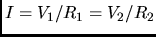
, i.e.
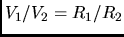
the total voltage drop V is "partitioned" along the two resistor in proportion to the
resistors relative values. This is a very important result (maybe the most important tool
to understand serial circuits), and can be re-expressed in the following way : when
a current I flows through a resistor R, then the voltage drop across R is given by
V = IR. You might say that there is nothing new here, we have just re-written Ohm's
Law, but in reality we are learning something new. Specifically, what we learn is
that if we know what is the current in a branch of a circuit, we can immediately find
out what is the voltage drop across each individual resistor, and we can also
determine how much power each resistor consumes (i.e. by how much it will heat up).
To appreciate this, let us go back
to Conceptual Example 7, discussing the importance of choosing the correct extension
cord for your heater. The situation is the following : you have a voltage source V
(e.g. your household 120V) an electric heater, which effectively is just a resistor
R (which will then produce power at the rate  ) and and extension cord, whose
resistance, albeit small with respect to R, is not zero, we will call it r. The
question is : how much does the extension cord heat up, i.e. how much power is
dissipated by its resistance r? We can give two answers, P = V
) and and extension cord, whose
resistance, albeit small with respect to R, is not zero, we will call it r. The
question is : how much does the extension cord heat up, i.e. how much power is
dissipated by its resistance r? We can give two answers, P = V /r or P = I
 r,
but we must be careful in interpreting the meaning of I and V
r,
but we must be careful in interpreting the meaning of I and V : I is the
total current through the cord (and the heater), but V
is not the total voltage of 120 V, it is only the voltage drop
across the cord itself. The value of I is determined not so much by the cord
but mostly by the heater. We have in fact I = V/(R+r)V/R, the cord plays a
negligible role in determining the total current. But the voltage drop across the cord does
depend on its resistance r, according to V = Ir . In conclusion, both apparently
contradictory expressions for the dissipated power lead to the same result, i.e. we
want r to be as small as possible:
: I is the
total current through the cord (and the heater), but V
is not the total voltage of 120 V, it is only the voltage drop
across the cord itself. The value of I is determined not so much by the cord
but mostly by the heater. We have in fact I = V/(R+r)V/R, the cord plays a
negligible role in determining the total current. But the voltage drop across the cord does
depend on its resistance r, according to V = Ir . In conclusion, both apparently
contradictory expressions for the dissipated power lead to the same result, i.e. we
want r to be as small as possible:
- from P=Ir: given that I is (almost) independent of r, to minimize the heating
of the cord one needs to minimize r
- from P=V/r: a small r will make V to be small, and this will minimize
the power, since P goes like the square of V
Thinking again of our equivalence between a (battery+resistance) circuit and
(water pump+mill wheel), we can interpret a circuit with two series resistors
as a configuration with two wheels at two different levels : the pump (battery)
brings the water (charges) to a high potential; falling down, the water first gives
part of its potential energy to the first wheel (charges dissipate some of their
potential in the first resistor) and then its remaining potential energy to the second
wheel (second resistor). The relative values of the resistors are equivalent to the
relative heights at which the two wheels are positioned.
The issue of non-negligible resistance of conductors, and the consequent loss of
power, plays an important role in the long distance transmission of electricity
(power lines) and is the main reason behind the practice of transmitting electricity
at a very high voltage.
Another important issue related to voltage drops and small resistances is related to the
internal resistance of batteries and the like. From I = V/R, you might wonder what would
happen if you had a battery of voltage V, and you connected directly the two terminals,
so as to have infinitesimally small resistance in the circuit. Would the current
approach infinity? Certainly not, the main reason being that the battery itself has its own
internal resistance, which is very small (a few
 ), but not zero.
Shorting the terminals of a 12 V battery would give, albeit for a very short time, a current
of many thousand amps ! Another consequence of the internal resistance is that the voltage
available from a battery depends on the amount of current coming out of the battery.
To understand this, it is useful to think of a battery as the combination of a perfect voltage
source, with no internal resistance, followed by a resistance equal in value to the actual
internal resistance. Suppose that, when measured in an open circuit, the battery is providing
a voltage V. If we then use the battery to send some current I to a circuit, the voltage drop
across the internal resistance will be
As a consequence, the actual voltage available from the battery will be
), but not zero.
Shorting the terminals of a 12 V battery would give, albeit for a very short time, a current
of many thousand amps ! Another consequence of the internal resistance is that the voltage
available from a battery depends on the amount of current coming out of the battery.
To understand this, it is useful to think of a battery as the combination of a perfect voltage
source, with no internal resistance, followed by a resistance equal in value to the actual
internal resistance. Suppose that, when measured in an open circuit, the battery is providing
a voltage V. If we then use the battery to send some current I to a circuit, the voltage drop
across the internal resistance will be
As a consequence, the actual voltage available from the battery will be  : the
more current you draw out of the battery the less voltage it gives you.....
: the
more current you draw out of the battery the less voltage it gives you.....
Resistors in parallel
To analyze a circuit with two parallel resistors, we need to keep in mind that both branches
are subjected to the same voltage difference, and that the sum of the current in the two
branches must be equal to the total current in the circuit. We then have
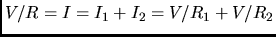
,
therefore
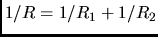
, or, if you prefer,
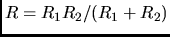
This result shows that the combination of two resistances in parallel has less overall
resistance than each individual one. This should not be too surprising : I can send more water
through two (even narrow) channels than through a single one.....
In a parallel circuit the current is divided inversely to the resistance,
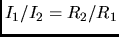 , this should not be surprising, obviously more current will
flow through the less resistive channel.
, this should not be surprising, obviously more current will
flow through the less resistive channel.
When dealing with more complicated mixtures of serial and parallel resistors, it is useful to
examine the circuit in sections, gradually replacing a set of serial or parallel
resistors with a single one having the correct value of global resistance.
When analyzing even more complex cases, one needs to apply Kirchhoff rules :
I will skip them, but you should at least read the book to get a feeling for what they
are.
Measuring Voltages and Currents
To start : it is not easy to actually measure a voltage, while it is fairly straightforward
to measure a current, therefore we actually measure voltages by measuring a current and
applying Ohm's Law. We have to defer to a later lecture an explanation of how the measuring
device actually works, and how we can get a needle deflection proportional to the current
going through the instrument. For the purpose of the discussion following, we can treat the
measuring instrument as a black box with two terminals that we connect to the circuit we want
to measure; and of course this black box will have its own internal resistance. But another
factor to keep in mind is that, as much as possible, you want to prevent the act of measuring
from interfering with the working of the circuit. With these preambles, we can now analyze the
procedures for measuring currents and voltages.
Current measurements
To measure the current through some section of a circuit, you simply insert your instrument in
series in the circuit and determine the current going through the instrument. But, in practice,
when you do this you add an extra resistance to your circuit, and this is going to affect the
total current. To minimize this effect, you would like your current measuring
instrument to have negligible resistance, or at least resistance very small compared to the
overall circuit resistance. This might sound feasible in principle, but it poses a practical
problem : how could one use the same instrument to measure accurately currents over a wide
range? If my instrument has a full scale of, e.g., 1 A, I will not read accurately currents in
the mA range, or if I choose, e.g., 10 mA as the scale full range, I will not be able to
measure currents larger than that. The solution to this problem is to include with the basic
measuring instrument a set of resistor (shunt resistors) that can be inserted in
parallel with the instrument. When I want to measure a very small current, I don't use any
shunt resistor and send all the current through the instrument. To measure larger currents, I
put a small resistor in parallel with the instrument; most of the current will flow through
the shunt, and only a small fraction through the instrument. But this small fraction will still
be proportional to the total current I want to measure (water analogy : how to measure the
total flux of water in a large river? open a small canal to the side and measure the flow
through the canal. Knowing the relative size of the river and the canal cross-sections I can
work out the total flux).
Voltage measurement
As mentioned before, to measure the voltage difference between two points of a circuit, the
procedure is to join the two points with your instrument, and measure the current going through
it. In other words, your instrument has to be inserted in parallel between the two
points. Once again we want to prevent our act of measuring from interfering with the system.
If there is a given voltage drop between two points in the absence of the instrument, inserting
the instrument will introduce an additional resistance in parallel to the original one, and this will
decrease the voltage drop (as two resistors in parallel allow more current, they have less
overall resistance than each individual one).
To minimize this effect,we want the current flowing through our
measuring instrument to be as low as possible, therefore an ideal voltmeter should have
a resistance much larger than that of the circuit under exam. Once again we need to face the
problem of covering a wide range of voltages with a single instrument. To this purpose, a
voltmeter is equipped with a set of resistances that can be put in series with the actual
instrument. When measuring a small voltage, only a small current will go through the
instrument, and no additional resistance is needed. But if the voltage difference is very
large, we need to limit the current going through the meter, and we do so by inserting a
suitable resistance in series with it.
Electricity and you
A few facts :
- what is bad for you, is not voltage but current. You can have a very large
 between two points of your body, but if the current flowing is not very large (i.e. if the
resistance is large) you will not suffer too serious consequences.
between two points of your body, but if the current flowing is not very large (i.e. if the
resistance is large) you will not suffer too serious consequences.
- electric current is particularly bad for you if it goes through your heart. If you work
on a live circuit, the worse thing you could do is to work on it with one hand while holding e.g.
the water pipes with the other: electric current would flow from one arm to the other, right
across your chest (experienced electricians are used to operate on a live circuit with one
hand only, while avoiding any contact of the other hand)
- there is a slight inaccuracy in the book's discussion of the grounding of household
appliances. If you touch the casing of, e.g., a drier which is in contact with live
wire, some current would go through your body even if the appliance is grounded (the book
says that no charge would flow through your body). The situation can be interpreted as a
two-branch parallel circuit, where one branch is the ground connection through a good
conductor, and the other branch is your body. From what we have learnt before, current would
flow through both branches, but in inverse proportion to the relative resistances (and a
proper grounding connection has obviously much less resistance than your body).
Circuits with capacitors
Do you remember the rule : resistors in series see the same current, while resistors
in parallel see the same voltage? The (almost) same rule applies to capacitors ,the
only difference being that, when dealing with capacitors, instead of current we
should think in terms of charge (a capacitor has a non-conducting gap between its
plates, therefore no current can go through it). But the expressions that we get when
applying the rule to series and parallel capacitors are the opposite of what we get for
resistors. Let's see how .
- parallel capacitors : if two capacitors C
 and C
and C are connected in parallel
in a circuit containing a voltage source V, they will acquire charges q and q
according to
are connected in parallel
in a circuit containing a voltage source V, they will acquire charges q and q
according to  and
and  . If q is the total charge, we can then
write
where C is the total capacitance of the system. We then see that, for parallel capacitors,
the total capacitance is given by the sum of the individual capacitances
(this is not so surprising, if I think of the water analogy, the total capacity of two
containers with the same water level will be the sum of the individual capacities).
. If q is the total charge, we can then
write
where C is the total capacitance of the system. We then see that, for parallel capacitors,
the total capacitance is given by the sum of the individual capacitances
(this is not so surprising, if I think of the water analogy, the total capacity of two
containers with the same water level will be the sum of the individual capacities).
- series capacitors : the fact that series capacitors contain equal amounts of
charge is less obvious, and there is no easy water analogy. But if we believe that
this is what is happening, then, if V and V
 are the voltages across the
capacitors, we can write
showing that the expression for series capacitors resembles the one we had found for
parallel resistors....
are the voltages across the
capacitors, we can write
showing that the expression for series capacitors resembles the one we had found for
parallel resistors....
Question : what happens when connecting batteries in series or in parallel ?
Charging and discharging a capacitor
Remember what happened when we charged two capacitors with a battery and then we discharged
one by joining the terminals with a screwdriver and the other connecting it to a light bulb?
It is clear that the time to discharge a capacitor will depend upon
- the value of the capacitance (since a larger capacitance contains more charge)
- the value of the resistance through which we are discharging the capacitor
(a big resistance will limit the current, i.e. the rate of charge flow per unit time)
It is rather intuitive that also the time to charge a capacitor will have a similar
dependence upon R and C. A straightforward application of calculus would show that the charging
and discharging take place according to
- charging :
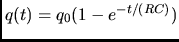
- discharging :
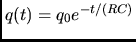
The quantity RC (would you have guessed that ohms x farads = seconds?) is called the
time constant of the RC circuit, as it controls the rate of charging/discharging. If you
are interested in the voltage across the capacitor plates
during the charge or discharge process, it is given by V(t) = q(t)/C.
Read this only if you are calculus savvy and curious
Where does the exponential function come from?
From V(t) = I(t)R, V(t) = q(t)/C and I(t) = dq/dt, we get
q(t) = RC dq(t)/dt. The solution to this "differential equation" is (apart from the
constant factors) a function that is equal to its derivative: and this is in fact the
fundamental property of the exponential function...
Next: About this document ...
Sergio Conetti
2003-02-06