


Next: About this document ...
Chapter 23
RCL circuits
When dealing with Alternating Currents, the presence of inductors and capacitors in the circuit generates all
sorts of new behaviours. Let's first examine each situation separately :
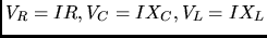
- AC circuit with resistance only : in this case the circuit behaves like a DC circuit. We
have
Two things to notice are
- the rms current is independent of the AC frequency f
- voltage and current are always in phase, i.e. when one has a maximum, a minimum or a zero, so
does the other.
- AC circuit with capacitance only : to start, let's notice that in a circuit with a capacitor
there can be
no DC current. If we connect a capacitor to a battery, there is some current while the battery is charging
up the capacitor, but then the current stops. But what if we connect a capacitor to a source of Alternating
Voltage? As the voltage reverses the capacitor sequentially charges, discharges and then charges up to the
opposite polarity. Even though there is no current across the capacitor's gap, there is an alternating
current in the circuit.
What about the relation between voltage and current across the capacitor's plates? If
we remember the ( ) expression for the charging of a capacitor, we notice that the charging up is
faster
at the beginning (i.e. when the voltage between plates is near zero) and it slows down as the voltage approaches
its maximum value. In other words voltage and current are 90
) expression for the charging of a capacitor, we notice that the charging up is
faster
at the beginning (i.e. when the voltage between plates is near zero) and it slows down as the voltage approaches
its maximum value. In other words voltage and current are 90
 out of phase, with the
current LEADING the voltage. This can be expressed as
And what is the relation between
out of phase, with the
current LEADING the voltage. This can be expressed as
And what is the relation between  and
and  (or between
  and
and  ) ? It could be seen
that a capacitor behaves like a resistance with the effective resistance (which goes under the name of
capacitive reactance
) ? It could be seen
that a capacitor behaves like a resistance with the effective resistance (which goes under the name of
capacitive reactance  given by
and
from this we see that
- the "resistance" is inversely proportional to the capacitance
- the "resistance" does depend (inversely) on the frequency of the voltage source ( a good way to
remember this is to think in terms of DC current : the "frequency" of a DC current is zero, and in this case the
capacitance presents infinite resistance to the current)
- AC circuit with inductance only : we can immediately guess that the "resistance" to the
current will be directly related to the frequency : a fast changing voltage induces an opposing emf, and the
faster is the change the larger the effect. And in fact one could derive the result
with

 being the inductive reactance.
What about the relative phase of current through the inductor and voltage across it? Here, the reasoning is the
following:
being the inductive reactance.
What about the relative phase of current through the inductor and voltage across it? Here, the reasoning is the
following:
the self-induced emf depends on the rate of change of the current (remember: emf = -L
 ). The sine
function changes slowly near a peak and quickly near a zero. Following this line of thought would show that
the current is
). The sine
function changes slowly near a peak and quickly near a zero. Following this line of thought would show that
the current is  out of phase, with the current LAGGING the voltage. In formulae
Another important property of a purely capacitive or a purely inductive circuit is that in both cases the power
consumption is zero. One could verify this by computing the overall value of P=IV over a whole cycle, and
realizing that there are equal negative and positive contributions. In physical terms, during a positive power
period the capacitor (or inductor) absorb electric power from the voltage source, during a negative cycle
the energy is released back.
We are now ready to understand a (serial) circuit including R, C and L. To start, we can get
an intuitive feeling for the dependence of current upon the frequency of the oscillating voltage:
when the frequency approaches zero, so will the rms current because of the effect of the capacitance C. Similarly, at very
high frequencies, the rms current will be suppressed by the effect of the inductance L. If a (positive) function goes to zero
at both ends of its range, there must be at least one intermediate value of the frequency for which the rms current
reaches a maximum. As we will soon see, this is the condition of resonance.
To get a deeper insight in the behaviour of an RLC circuit we have to take into account the relative phases of currents and
voltages across the various circuit elements. This is best done by introducing the concept of phasors.
To describe the behaviour of current or voltage in an AC circuit, we introduce a vector of magnitude equal to the maximum
amplitude of current or voltage, and we let this vector rotate in the x-y plane with uniform angular velocity
 . If I or V vary with the
  behavior typical of AC, then, at all times,
the instantaneous values of I and V are given by the projection of their phasor onto the y-axis. Remembering what we had
learnt about the relative phases of I and V when dealing with Capacitances and Inductances, we can see that, in purely
capacitive or inductive circuits, the V phasor will always make a 90
behavior typical of AC, then, at all times,
the instantaneous values of I and V are given by the projection of their phasor onto the y-axis. Remembering what we had
learnt about the relative phases of I and V when dealing with Capacitances and Inductances, we can see that, in purely
capacitive or inductive circuits, the V phasor will always make a 90 angle with the I phasor, with the V phasor preceding
(following) the I phasor for inductive (capacitive) circuits.
angle with the I phasor, with the V phasor preceding
(following) the I phasor for inductive (capacitive) circuits.
What we want to obtain is the equivalent of Ohm's Law for an RLC circuit, i.e. an expression of the type
where the quantity Z, the "impedance", is the equivalent of the resistance for the case of Alternating Currents.
From what we had learnt earlier, you might be tempted to conclude that
 , but this is not
correct since it does not take into account the fact that, at any point in the circuit, the voltages due to the R,L,C
components are not in phase.A way to account for this, is to add vectorially the
, but this is not
correct since it does not take into account the fact that, at any point in the circuit, the voltages due to the R,L,C
components are not in phase.A way to account for this, is to add vectorially the
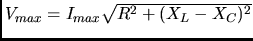
 voltages: the magnitude
of the vector sum will give us the maximum voltage in the circuit, and its projection on the y-axis will correspond to the
voltage instantaneous value. It is fairly straightforward to get the vector's sum magnitude :
voltages: the magnitude
of the vector sum will give us the maximum voltage in the circuit, and its projection on the y-axis will correspond to the
voltage instantaneous value. It is fairly straightforward to get the vector's sum magnitude :
- as
 and
and  are both at right angle with respect to the current, but in opposite directions, they are always
180 from each other, and the magnitude of their sum is
are both at right angle with respect to the current, but in opposite directions, they are always
180 from each other, and the magnitude of their sum is
 .
.
 is always perpendicular to the
 line, so that the total magnitude is given directly
by Pythagoras :
line, so that the total magnitude is given directly
by Pythagoras :
But we also have
 , therefore (after a couple of simple steps)
and also
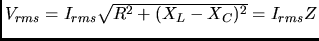
which is the expression we were looking for, showing that the total impedance of a serial RLC circuit is given by
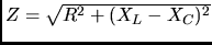 .
.
A few more things we can learn from the phasor diagrams :
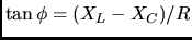
- the relative phase angle
 between current and voltage is given by
- one could also see that
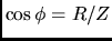 , which is useful in determining the average power dissipation of an RCL
circuit:
, which is useful in determining the average power dissipation of an RCL
circuit:
remembering that C and L do not consume any power, one has
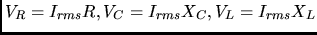
Problem : we knew how to estimate the voltage drop across each resistor when dealing with DC resistive circuits. What about
an RLC AC circuit? The procedure is the following :
- first compute the total impedance Z
- next compute

- now you can do
Example :

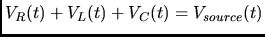
If we do the calculations, we find that the sum of the three voltage drops is not equal to 90 V. How can this be ?
The answer is that the rms voltages are defined to be always positive, while, at any instant, the real voltages are out of
phase with each other and can be positive or negative. If we were to compute at any instant t the actual values of the
voltages we would always get
Resonance
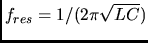
We can now verify the intuitive result we had discussed earlier, i.e. that in an RLC circuit there is a special value of the
frequency for which the current is at a maximum (i.e. the impedance is at a minimum). The expression for the impedance shows
that Z reaches its minimum value when  , i.e.
Notice that if there was no resistance (R=0), at the resonant frequency the current would become infinitely large. In reality
resistances, even if small, can never be completely neglected, but it is still true that at the resonant frequency one can
achieve very large values of current. And the smaller the resistance, the "sharper" the width of the resonance.
LC resonance is exploited in many electronics application. For ewxample, the tuning circuit of your radio is effectively an
LC circuit: a variable capacitance is connected to the motion of the tuning dial, and by moving it you seek the LC resonant
value corresponding to the broadcast frequency of the station you want to listen to.
Semiconductors and Transistors : read and retain as much as possible, even though the subject
will not be included in the next tests
Next: About this document ...
Sergio Conetti
2003-03-11