revised October 29, 1996
ELECTROMAGNETIC WAVES
INTRODUCTION
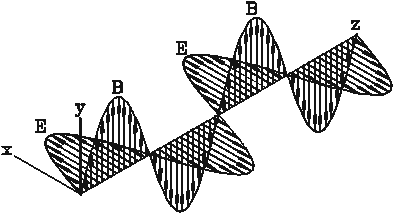
Electromagnetic waves are time varying electric and magnetic fields that are coupled to each other and that travel through empty space or through insulating materials. (Electromagnetic waves cannot travel through conducting materials although they can travel along their surfaces). Electromagnetic waves are transverse waves, i.e. the directions of their electric and magnetic fields are perpendicular to the direction in which the wave travels. Figure 1 shows a periodic electromagnetic wave traveling in the z-direction; the electric and magnetic fields are, as always, perpendicular to each other. For periodic electromagnetic waves the frequency and the wavelength are related through

Figure 1: Periodic electromagnetic wave, E=vector of the electric field, B=vector of the magnetic field.
c = (1)
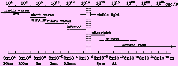
where l is the wavelength of the wave, xx is its frequency, and c is the velocity of light. The spectrum of electromagnetic waves spans an immense range of frequencies, from near zero to more than 1030 Hz (the Hertz, abbreviated Hz, is a unit of frequency. 1 Hz corresponds to 1 cycle per second). A section of the electromagnetic spectrum is shown in Fig. 2.

Figure 2: Section of the electromagnetic spectrum.
Electromagnetic waves are produced whenever electric charges are accelerated. This makes it possible to produce electromagnetic waves by letting an alternating current flow through a wire, an antenna. The frequency of the waves created in this way equals the frequency of the alternating current. (The light emitted by a light bulb is caused by thermal motion that accelerates the electrons in the hot filament sufficiently to produce visible light.) The inverse effect also happens: if an electromagnetic wave strikes a wire, it induces an alternating current of the same frequency in the wire. This is how the receiving antennas of a radios or television sets work. As one might expect, an antenna is most efficient when its length is of the order of the wavelength of the waves emitted or received. (The waves used for TV transmission, for example, have wavelengths of the order of one meter, which is also the size of a typical TV antenna.)
The waves that you will be using in this experiment have a frequency of about 1010 Hz, corresponding to a wavelength of 3 cm. This relegates them to the so called microwave part of the spectrum. This name is to be understood historically: In the early days of radio the wavelengths in use were of the order of hundreds, even thousands, of meters. Compared with these waves, those in the cm region, which were first used in radar equipment during W.W.II, were indeed microwaves.
In this experiment the emphasis is not so much on quantitative measurements as on qualitative observations. Please record all your observations carefully and concisely in your journal. If you do this, your report can be quite brief.
APPARATUS
Thornton APS-101 power-amplifier supply with MWG-102 microwave generator module, second APS-101 with FGR-100 function generator, microwave detector diode with leads, 6 range meter, 2 speakers, 2 aluminum reflector angles, aluminum double slit hood, polarizer comb, meter stick, plastic ruler, masking tape, paraffin cylinder.
WHAT TO DO
Examine the microwave generator. Look into the horn and notice the narrow slot crossed by what looks like a plastic rod. Inside this rod is a Gunn diode, a solid state device. When a dc voltage is applied to a Gunn diode current flows through it in bursts at regular intervals. For your diode these bursts come about 10-10 sec apart causing, in addition to the dc current, an ac current of 1010 Hz. This frequency corresponds to a wavelength of 3 cm. The closed metal box behind the diode, which you can see if you remove the generator module from the APS101 and look through the plug slot, is 1.5 cm or 1/2 wavelength long. This makes it resonant at a frequency of 1010 Hz. As a result a large ac voltage, oscillating at that frequency is present across the slot, and a wave is radiated from the horn. The electric field of this wave points in the direction across the slot, parallel to the Gunn diode. The polarization of an electromagnetic wave is determined by the direction of the electric vector. In your apparatus the wave is polarized in the direction parallel to the Gun diode. The magnetic field of the wave points along the slot, encircling the ac current in the Gun diode.
Plug the generator onto the AS101 and turn on the power. Experimental setup
Locate the microwave detector diode. It looks like a radio resistor with a pair of wires soldered to its leads and is mounted at the end of a plastic ruler. The stiff leads on this diode are cut to 1/2 wavelength or about 1.5 cm. When the electric field of the wave strikes it, an ac voltage of 1010 Hz is induced across the diode. Diodes pass current much more readily in one direction than in the other. As a result a dc voltage, that can be measured with a dc voltmeter, is built up across the diode. Plug the long cord from the diode into the 6range meter on the A scale. Position the diode approximately 15 cm from the horn, while keeping your hand out of the way, (Any conductor in the vicinity, e.g. a piece of metal, even your hand, will reflect waves and may give you spurious results.) When the diode leads are aligned parallel to the Efield of the wave, you should get an indication on the meter. Rotate the diode and verify that it is sensitive to the polarization of the wave. An Efield perpendicular to the diode induces no voltage. Move the diode away from the horn. How far away do you still get a noticeable current through the meter?
(You can increase the sensitivity by amplifying the diode signal with the AS-101 amplifier as shown in Figure 3.
Fig.3:
Plug the diode leads into the input terminals of the AS101 and connect its output to the meter. You will probably want to use the 2 V range of the meter. Set the zero offset control to zero and the gain fairly high. Make sure the AC-DC switch is set on DC. Experiment with this setup until you can get a strong signal across a 60 cm gap between horn and diode.
Insert the comb of aluminum rods in the beam so that the rods are first parallel and then perpendicular to the direction of the E field. Watch the meter; try to explain your observations in terms of the Efield and the direction in which currents can flow in the rods?
Demonstrate that, just like light waves, microwaves undergo refraction as they pass from one medium into another: Place the 'cylindrical lens," i.e. the paraffin cylinder, between the microwave source and the detector, varying the distance to the detector. Can you find a focal point, the focal length of the 'lens'?
Set up the aluminum angle as a reflector, facing the horn at a distance of 45 cm. This will produce a standing wave. Slide the aluminum angle carrying the diode along the meter stick, noting the positions of maxima and minima of the signal strength, adjusting the gain of the amplifier as necessary. What is the wavelength you deduce from this measurement?

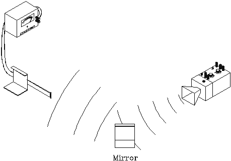
Figure 4: Interference of direct and reflected wave.
To demonstrate the wave nature of electromagnetic radiation in yet another way create an interference pattern by using the generator and its mirror image as two sources of coherent radiation as shown in Figure 4). If you move the aluminum angle along a line perpendicular to the line connecting horn and diode you should pick up a series of maxima and minima. This variation of the intensity at the detector is akin to radio "fading", an effect one often notices while receiving distant radio stations. There is a shell of partly ionized (and therefore conducting) gas surrounding the earth at an altitude of approximately 120 kilometers, the Heaviside layer. This region is part of the earth's "ionosphere", and is, due to its electrical conductivity, a good reflector of radio waves over a certain region of wavelengths. Radio waves that reach the receiver by way of the Heaviside layer can interfere constructively or destructively with those that reach it traveling along the earth's surface. Whenever the Heaviside layer drifts up or down the interference pattern will change, resulting in a change of intensity at the receiver. Short radio waves < 60 m), can travel long distances either by multiple reflections or by propagating along the surface of the Heaviside layer. This was not recognized by the "authorities" who gave the useless short wave band to radio amateurs who soon achieved unheard of feats of long distance communication.
Slide the double slit hood over the horn, creating two coherent microwave sources. Move the diode at a distance of about 20 cm from the horn at a right angle to the axis of the horn. Note the maxima and minima and make a measurement of the wavelength this way. The formula that describes the interference pattern is the same as the one used in the sound wave experiment.
Radio waves have much higher frequencies than audible sound waves. That makes it possible to vary their amplitude in proportion to the momentary amplitude of the sound, i.e. make them more or less intense in a pattern that reproduces the wave form of an audible signal. Hence, the term A(mplitude) M(odulated) or AM radio. You can modulate the output of the microwaves transmitter with an ac voltage from the function generator. When the modulated wave is received by the detector diode the rectified voltage, which is proportional to the amplitude of the radio wave, varies in a pattern that reproduces the original modulation. This voltage can be amplified and used to drive a speaker.
Attach the function generator to the second AS101. Set the dc offset to zero and the gain to about 50. Connect its red output terminal of the AS-101 to the modulation input terminal of the microwave generator and the black terminal to one of the ground terminals on the first AS101. Connect a speaker in parallel to the meter to detect the time varying component of the voltage from the receiver diode. Vary the frequency of the oscillator and wave your hand in front of the diode to convince yourself that the sound from the speaker is indeed being carried by the radio wave.
If you wish, you can set up a voice transmitter as follows: Remove the OSC-100 module from the second AS-100 and connect the second speaker to its input as a microphone. After some experimentation you may be able to communicate over a short distance with another group.
Try to receive a local radio station using the separate little diode that you are given, (not the expensive microwave diode that is mounted on the aluminum angle!!!!) You can make your "receiver" more sensitive for such stray signals by attaching an antenna, that is a wire of 1 or 2m length to one end of the diode. WARNING: Do not connect your "antenna" to any of the electrical outlets in the laboratory, they may carry high voltages.