 Set 9
Set 9
 Assignments
 Set 7
Set 7
Phys 312 - Assignment 8 - Due 1 April 99
1.
Fundamental constants from LED data. In class, we measured the
threshold voltage to get appreciable light from various LED's (red, yellow,
green, blue). Use these data to obtain a rough estimate of h/e, assuming
that all the energy eV gained by an electron passing through the LED is
transferred to a single photon. Plot (by hand) the data to check this simple
assumption.
| Wavelength | Frequency | Voltage |
| in nm | in 1014 Hz | in volts |
| 660 | 4.54 | 1.35 |
| 630 | 4.76 | 1.46 |
| 590 | 5.08 | 1.58 |
| 565 | 5.31 | 1.66 |
| 450 | 6.66 | 2.28 |
2.
Circuit parameters. A general circuit is characterized by the
three quantities R, C, L.
- (a)
- What are the dimensions of these quantities in the SI? Optional: what
are their dimensions in the gaussian system (they are a lot simpler and more
intuitive, but in this course we have agreed to use SI).
- (b)
- What are the dimensions of the product LC? What is its physical
meaning?
- (c)
- What are the dimensions of the product RC? What is its physical
meaning?
- (d)
- What are the dimensions of R/L? What is its physical meaning?
- (e)
- Form a dimensionless combination of R, C, L. What is its
physical meaning?
3.
Passive low pass filter. As I mentioned in class, one stage of
an archaic AM receiver consists of a low pass filter which removes the RF (radio
frequency) carrier wave, leaving the AF (audio frequency) signal. The
simplest passive filter (i.e., a filter which does not involve active
elements such as transistors), consists of a resistor and a capacitor.
- (a)
- Sketch this filter
- (b)
- Show that
|  |
(1) |
Plot this transfer function and show that it has the right properties
to function as a low pass filter.
- (c)
- Choose appropriate values of R and C for an AM receiver.
- (d)
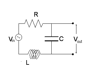
- Our simple filter has a very slow "roll-off"; ideally, one would
like a "brick wall" transfer function which is 1 up to some frequency
 and zero otherwise. Some improvement is obtained by
incorporating an inductor into the filter, as discussed in class and sketched here.

- (e)
- Find the transfer function for this filter. Show that the response at
low frequencies is the flattest when
 . This can be done
graphically by plotting the transfer function as a function of a
dimensionless frequency for several values of a dimensionless parameter that
is proportional to L. Note that for L=0 we are back to the previous case.
- (f)
- How does the transfer function behave at high frequencies?
4.
Using CMOS technology (with enhancement MOSFETS), as in Bloomfield,
page 481, draw the circuit for an OR gate. Make four replicas of your
drawing and indicate explicitly the voltage (or charge) on all the gates and
nodes (you may just color the ones that are positive) for the four different
possible inputs. Verify that the output is in agreement with the truth table
for OR.
Vittorio Celli
3/6/1999

 and zero otherwise. Some improvement is obtained by
incorporating an inductor into the filter, as discussed in class and sketched here.

 . This can be done
graphically by plotting the transfer function as a function of a
dimensionless frequency for several values of a dimensionless parameter that
is proportional to L. Note that for L=0 we are back to the previous case.