


Next: About this document ...
Phys 312 - Assignment 8 - Due 26 Mar 98
- 1.
- Fundamental constants from LED data. In class, we measured the
threshold voltage to get appreciable light from various LED's (red, yellow,
green, blue). Use these data to obtain a rough estimate of h/e, assuming
that all the energy eV gained by an electron passing through the LED is
transferred to a single photon. Plot (by hand) the data to check this simple
assumption.
- 2.
- Circuit parameters. A general circuit is characterized by the
three quantities R, C, L.
- (a)
- What are the dimensions of these quantities in the SI? Optional: what
are their dimensions in the gaussian system (they are a lot simpler and more
intuitive, but in this course we have agreed to use SI).
- (b)
- What are the dimensions of the product LC? What is its physical
meaning?
- (c)
- What are the dimensions of the product RC? What is its physical
meaning?
- (d)
- What are the dimensions of R/L? What is its physical meaning?
- (e)
- Form a dimensionless combination of R, C, L. What is its
physical meaning?
- 3.
- Passive low pass filter. As I mentioned in class, one stage of
an archaic AM receiver consists of a low pass filter which removes the RF (radio
frequency) carrier wave, leaving the AF (audio frequency) signal. The
simplest passive filter (i.e., a filter which does not involve active
elements such as transistors), consists of a resistor and a capacitor.
- (a)
- Sketch this filter
- (b)
- Show that
| 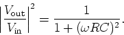 |
(1) |
Plot this transfer function and show that it has the right properties
to function as a low pass filter.
- (c)
- Choose appropriate values of R and C for an AM receiver.
- (d)
- Our simple filter has a very slow "roll-off"; ideally, one would
like a "brick wall" transfer function which is 1 up to some frequency
 and zero otherwise. Some improvement is obtained by
incorporating an inductor into the filter, as discussed in class. Sketch
this filter.
and zero otherwise. Some improvement is obtained by
incorporating an inductor into the filter, as discussed in class. Sketch
this filter.
- (e)
- Find the transfer function for this filter. Show that the response at
low frequencies is the flattest when
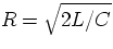 . This can be done
graphically by plotting the transfer function as a function of a
dimensionless frequency for several values of a dimensionless parameter that
is proportional to L. Note that for L=0 we are back to the previous case.
. This can be done
graphically by plotting the transfer function as a function of a
dimensionless frequency for several values of a dimensionless parameter that
is proportional to L. Note that for L=0 we are back to the previous case.
- (f)
- How does the transfer function behave at high frequencies?
- 4.
- Fourier series.
- (a)
- Derive the Fourier series for the square wave of period
 defined by the periodic repetition of
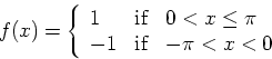
Note that f(x) is discontinuous at x=0 and at  . In this case,
the Fourier series reduces to a series of sines or cosines (which?); write
down both the complex exponential form and the sine or cosine form of the
series.
. In this case,
the Fourier series reduces to a series of sines or cosines (which?); write
down both the complex exponential form and the sine or cosine form of the
series.
- (b)
- Examine the convergence of the Fourier series to the square wave by
plotting the sum of the first few terms. How many Fourier amplitudes are
needed to produce an accurate square wave? Look carefully at what happens
near x=0.
- (c)
- What is the bandwidth for this signal?
- 5.
- Power spectrum. Here we combine the results of problems 3 and 4.
- (a)
- What is the normalized power spectrum of the square wave
 ?
?
- (b)
- If the square wave is passed through the filter of problem 3a, what
is the output signal Vout? Make an accurate plot of
 as a function of t/T for a representative value of
- (c)
- Same question for the filter of problem 3d, when it is optimized for
low-pass behavior.
- (d)
- What is the normalized power spectrum of the filtered signal in the
two cases ? Formulas are sufficient.
- (e)
- What is the bandwidth of the filtered signal in the two cases?
Next: About this document ...
Vittorio Celli
3/19/1998