INTRODUCTION
All imaging methods use of some kind of wave phenomena in order to make the imaging process work. In the very process of seeing or visualizing with our eyes we are using 'light' or optical waves. Other forms of imaging such as ultrasound, which for example is used in medical imaging extensively utilize sound waves for producing the image. In order to better appreciate and understand the many nuances and effects that arise in various imaging methods it is instructive to review the basic concepts behind waves and wave phenomena. Apart from light and sound the next most common type of wave which most people are familiar with are mechanical waves - such as waves on a string. Common examples of stretched strings include those on a guitar or simply a rubber band held between two fingers.
There are many phenomena common to all the above types of waves. These are - reflection, refraction, interference, diffraction, polarization etc.
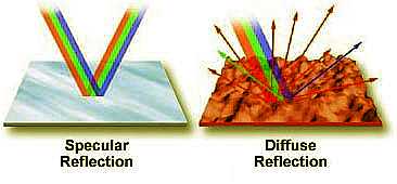
Reflection of a wave occurs whenever a boundary that does not absorb the waves energy is encountered. The incoming wave is referred to as an incident wave and the wave that is bounced from the surface is called the reflected wave. For example, when visible white light emitted by a flashlight is directed onto the surface of a mirror at an angle (incident) the light is reflected back into space at another angle (reflected) that is equal to the incident angle. Thus, the angle of incidence is equal to the angle of reflection generally. This concept is often termed the law of reflection. In the case of a light wave the best surface for reflection is a very smooth surface such as a glass mirror or polished metal. The amount of the wave reflected by the boundary is very dependent upon the texture of the boundary. When surface imperfections are smaller than the wavelength of the incident wave (as in the case of a smooth mirror), virtually all of the wave is reflected. However, in the real world most objects have convoluted surfaces that exhibit a diffuse reflection, with the incident wave being reflected in all directions. Thus the reflection of waves can be categorized into two types: specular reflection defined as a wave reflected from a smooth surface at a definite angle ( as in the case of the flashlight and mirror) and diffuse reflection, which is produced by rough surfaces that tend to reflect in all directions. Diffuse reflection occurs more often than specular reflection
.
The diagram on the left illustrates specular and diffuse reflection. On the left, a mirror reflects the various components of white light almost equally and the reflected light emerges at the same angle as the incident light. The surface on the right, however, scatters light in all directions.
Refraction (or bending of the waves) occurs
whenever a wave passes from a one medium to another in which the speed with
which the wave can propagate suffers a change.  How much bending can occur is dictated by a number called the refractive index
defined as the relative speed at which the wave moves through (the final)
material with respect to a reference (initial) material. In
the case of light for example when light passes from a less dense medium (such
as air) to a more dense medium (such as water), the speed of the wave decreases.
Alternatively, when light passes from a more dense medium (water) to a less
dense medium (air), the speed of the wave increases. The angle of
refracted light is dependent upon both the angle of incidence and the
composition of the material into which it is entering. The concept of refractive
index is illustrated below for the case of light passing from air through both
glass and water. Both beams enter the denser material through the same angle of
incidence but come out at different angles since water has a lower refractive
index than glass.
How much bending can occur is dictated by a number called the refractive index
defined as the relative speed at which the wave moves through (the final)
material with respect to a reference (initial) material. In
the case of light for example when light passes from a less dense medium (such
as air) to a more dense medium (such as water), the speed of the wave decreases.
Alternatively, when light passes from a more dense medium (water) to a less
dense medium (air), the speed of the wave increases. The angle of
refracted light is dependent upon both the angle of incidence and the
composition of the material into which it is entering. The concept of refractive
index is illustrated below for the case of light passing from air through both
glass and water. Both beams enter the denser material through the same angle of
incidence but come out at different angles since water has a lower refractive
index than glass. 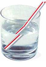 The index of refraction even for a given pair of materials need not be a
constant - for example it could change depending on the frequency of the
incident wavet. This phenomenon is termed dispersion. For example
with light waves as the wavelength increases, the refractive index
decreases. It is this fact that is responsible for the familiar splitting of
light into its component colors by a prism. One of the most common
manifestations of refracted light is the bent drinking straw placed in a glass
of water.
The index of refraction even for a given pair of materials need not be a
constant - for example it could change depending on the frequency of the
incident wavet. This phenomenon is termed dispersion. For example
with light waves as the wavelength increases, the refractive index
decreases. It is this fact that is responsible for the familiar splitting of
light into its component colors by a prism. One of the most common
manifestations of refracted light is the bent drinking straw placed in a glass
of water.
Critical Angle of Reflection
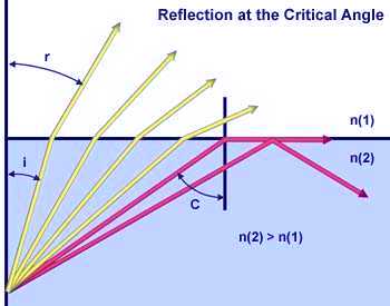 When light passes
through a medium of high refractive index into a medium of lower refractive
index, the incident angle of the light waves becomes an important factor. If the
incident angle increases past a specific value (dependent upon the refractive
index of the two media), it will reach a point where the angle is so large that
no light is refracted into the medium of lower refractive index, as illustrated
in the figure on the left. In this figure, individual light rays are represented
by either red or yellow colored arrows moving from a medium of high refractive
index (N(2)) to one of lower refractive index (N(1)). The four
yellow light rays all have an angle of incidence (i) low enough to pass
through the interface between the two media. However, the two red light rays
have incident angles that exceed the critical angle (approximately 41 degrees)
and are reflected either into the boundary between the media or back into the
high refractive index medium.
When light passes
through a medium of high refractive index into a medium of lower refractive
index, the incident angle of the light waves becomes an important factor. If the
incident angle increases past a specific value (dependent upon the refractive
index of the two media), it will reach a point where the angle is so large that
no light is refracted into the medium of lower refractive index, as illustrated
in the figure on the left. In this figure, individual light rays are represented
by either red or yellow colored arrows moving from a medium of high refractive
index (N(2)) to one of lower refractive index (N(1)). The four
yellow light rays all have an angle of incidence (i) low enough to pass
through the interface between the two media. However, the two red light rays
have incident angles that exceed the critical angle (approximately 41 degrees)
and are reflected either into the boundary between the media or back into the
high refractive index medium.
Many devices make use of the fact that light can be refracted, reflected, and focused. The most common example is a camera, which is designed to create sharp and focused images onto an emulsion of film to produce an accurate image. Other optical devices are microscopes and telescopes that allow us to view details that are invisible to the unaided human eye, regardless of whether they are located on the head of a pin or in a distant galaxy.
Interference: Another characteristic of waves is
their ability, given the right conditions, to interfere with one another. One of
the best examples of interference occurs in a film of oil floating on water.
Another example is the magnificent patterns in a soap bubble. The ever
changing display of colors in a bubble arises due the simultaneous reflection of
light from both the inside and the outside surfaces of the bubble. The two
surfaces are so close together that light reflected from the inner surface
interferes with light reflected from the outer surface. When the two sets of
reflected waves are combined that can remove or reinforce various parts of the
white light thus enhancing some colors and suppressing others. If the extra
distance traveled by the inner light waves is exactly the wavelength of the
outer light waves, then they will recombine constructively and bright colors of
those wavelengths will be produced. In places where the waves are out of step,
destructive interference will occur, canceling the reflected light (and the
color). The following figure demonstrates of how waves interfere with each
other. Consider a pair of waves from the same source that are traveling, for
example, in direction D. 
Assuming all of the criteria listed above are met, then the waves can interfere either constructively or destructively with each other. If the crests of one of the waves coincide with the crests of the other, the amplitudes are additive. If the amplitudes of both waves are equal, the resultant amplitude would be doubled. Such additive interference is called constructive interference (illustrated in the figure on the right).
If the crests of one wave coincide with the troughs of the other wave, the resultant amplitude is decreased or may even be completely canceled, as illustrated in the figure on the left. This is called destructive interference. The result is a drop in intensity, or in the case of total cancellation, blackness.
Sir Isaac Newton, the famous 17th century mathematician and physicist, was one of the first scientists to study interference phenomena. In his famous Newton's Rings experiment, he placed a convex lens of large curvature radius on a flat glass plate and applied pressure to hold the lens and glass plate together. When he viewed the plates through reflected sunlight, he observed a series of concentric light and dark highly colored bands of light similar to those illustrated in Figure 5. Newton recognized that the rings indicated the presence of some degree of periodicity and used this observation to suggest a wave theory of light. Despite this, Newton regarded light as a stream of particles. The rings occur because of a thin layer of air that exists between the curved convex and flat glass surfaces. Light reflected from the top and bottom surfaces of the glass is superimposed (combined) and produces interference patterns that appear as the colored rings.
Interference colors arising from stressed regions in materials can be easily observed in polarized light. The ruler in Figure 6 is made of plastic and is being observed through crossed polarizers. Under normal light, the ruler appears translucent with its graduations plainly visible. However, when viewed under polarized light, the ruler exhibits stress patterns that appear more profound in areas that are more highly deformed. This is due to a high degree of alignment of the long-chain polymer molecules that comprise the ruler. Note that the greatest degree of birefringence occurs near the hole on the left side of the ruler.
Other uses of interference are measurements made over long distances with lasers. In this case, the lasers can be used to measure very small distances over a range of many miles. This is accomplished by splitting the laser beam and reflecting it back from different surfaces. Analysis of the resulting interference fringes (upon recombining the separate laser beams) will yield a remarkably accurate calculation of the distance between the two objects.
Holograms also depend upon interference to produce their three-dimensional-like images. In reflection holograms, both a reference and object-illuminating beam are reflected onto a thick film from opposite sides. These beams interfere to produce light and dark areas that correspond to an image that appears three-dimensional. Transmission holograms use both the reference and object-illuminating beams on the same side of the film to produce a similar type of effect.
Diffraction of a wave occurs
when a wave passes by a corner or through an opening or a slit that is
physically the approximate size of, or even smaller than it's wavelength. A very
simple demonstration of diffraction can be conducted by slowly closing two
fingers while observing a lit incandescent lamp through the space between the
fingers. As the fingers approach each other and come very close together, you
begin to see a series of dark lines parallel to the fingers. The parallel lines
are actually diffraction patterns. This phenomenon can also occur when a wave is
"bent" around particles that are on the same order of magnitude as the
wavelength. The terms diffraction and scattering are
often used interchangeably and are considered to be almost synonymous.
Diffraction describes a specialized case of light scattering in which an object
with regularly repeating features (such as a diffraction grating) produces an
orderly pattern. In the real world most objects are very complex in shape and
should be considered to be composed of many individual diffraction features that
can collectively produce a random scattering of light. One of the classic and
most fundamental concepts involving diffraction is the single-slit optical
diffraction experiment, first conducted in the early nineteenth century. When a
light wave propagates through a slit (or aperture) the result depends upon the
physical size of the aperture with respect to the wavelength of the incident
beam. This is illustrated in the drawing below assuming a coherent,
monochromatic wave emitted from point source S, similar to light that
would be produced by a laser, passes through aperture d and is
diffracted, with the primary incident light beam landing at point P and
the first secondary maxima occurring at point Q. 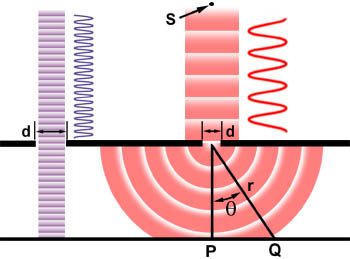
As shown in the left side of the figure, when the wavelength (l) is much smaller than the aperture width (d), the wave simply travels onward in a straight line, just as it would if it were a particle or no aperture were present. However, when the wavelength exceeds the size of the aperture, we experience diffraction of the light according to the equation:
sinq = l/d
Where q is the angle between the incident
central propagation direction and the first minimum of the diffraction pattern.
The experiment produces a bright central maximum which is flanked on both sides
by secondary maxima, with 
the intensity of each succeeding secondary maximum decreasing as the distance from the center increases. The graph on the left illustrates this point with a plot of beam intensity versus diffraction radius. Note that the minima occurring between secondary maxima are located in multiples of p.
Our discussions of diffraction have used a slit as the aperture through which light is diffracted. However, all optical instruments have circular apertures, for example the pupil of an eye or the circular diaphragm and lenses of a microscope. Circular apertures produce diffraction patterns similar to those described above, except the pattern naturally exhibits a circular symmetry.
Polarization: Apart from the direction in which a wave moves or propagates we can also identify another significant direction with most waves. This is the direction in which the wave is 'polarized'. In the case of the guitar string or rope oe waves on water the polarization direction is perpendicular to the direction of propagation. This is because the water molecules or the individual elements of the rope are moving up and down while the wave itself propagates forward. We refer to these types of waves as transverse waves. Sound waves on the other hand have the molecules of air moving back and forth in the same direction as the direction of propagation.
Polarization of light is very useful in many aspects of optical microscopy. The microscope configuration uses crossed polarizers where the first polarizer (termed: the polarizer) is placed below the sample in the light path and the second polarizer (termed: the analyzer) is placed above the sample, between the objective and the eyepieces. With no sample on the microscope stage, the light polarized by the polarizer is blocked by the analyzer and no light is visible. When samples that are birefringent are viewed on the stage between crossed polarizers, the microscopist can visualize aspects of the samples through light rotated by the sample and then able to pass through the analyzer. The details of polarized light microscopy are thoroughly discussed in our microscopy section of this primer.
Electromagnetic Waves: Many devices such as radio, TV, microwave oven etc. make use of electromagnetic waves. Radio waves, microwaves, visible light, and x rays are all examples of electromagnetic waves that differ from each other in wavelength.
(a) Longer wavelength; (b) shorter wavelength .
.
Electromagnetic waves are produced by the accelerated motion of electrically charged particles. These waves are also called "electromagnetic radiation" because they radiate from the electrically charged particles. They travel through empty space as well as through air and other substances.
Electromagnetic Spectrum - Electromagnetic
radiation exists in a range of frequencies called the electromagnetic spectrum.
As can be seen from the table below, each frequency has a specific wavelength
and as the frequency decreases, the actual length of the wave gets longer. Just
like we can only hear certain frequencies of sound, we can only see a small
portion of the electromagnetic spectrum - visible light. The visible spectrum,
as depicted below, has a wavelength range from 750 nanometers to 380 nanometers,
where one nanometer (nm) equals one-billionth of a meter. ![]()
The electromagnetic spectrum covers a wide range of wavelengths and photon energies. Light used to "see" an object must have a wavelength about the same size as or smaller than the object. Here is another representation of the Electromagnetic Spectrum
Classical vs. Quantum Ideas on energy: Thomas
Young a early 19th century physicist demonstrated interference showing that
light is a wave phenomenon. This was contrary to widely held beliefs of his time
that light is a stream of particles. Young conducted an experiment termed
"the Double-Slit experiment", in which he let sunlight coming through a
single slit to pass through two closely situated slits. 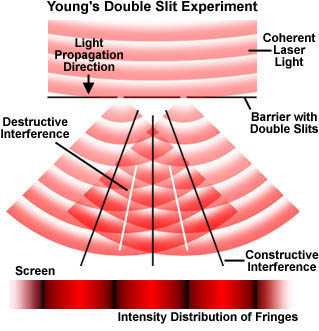 The basic setup of the double-slit experiment is illustrated in the
figure below. Instead of sunlight a laser beam is allowed to illuminate two
pinhole apertures that allow only some of the light to pass through. A pattern
of bright red and dark interference bands becomes visible. The key to this
experiment is the mutual coherence between the light diffracted from the two
slits at the barrier. Young achieved this coherence through the diffraction of
sunlight from the first slit, and we are using a coherent laser source for the
purposes of this discussion. As laser light is diffracted through the two
barrier slits, each diffracted wave meets the other in a series of steps, as
illustrated in Figure 4 (and graphically in the ). Sometimes the waves meet in
step (or in phase; constructive interference), sometimes they meet out of step
(or out of phase; destructive interference), and sometimes they meet partially
in step. When the waves meet in step, they add together due to constructive
interference and a bright area is displayed on the screen. In areas where the
waves meet totally out of step, they will subtract from each other due to
destructive interference and a dark area will appear in that portion of the
screen. The resulting patterns on the screen, a product of interference between
the two diffracted beams of laser light, are often referred to as interference
fringes.
The basic setup of the double-slit experiment is illustrated in the
figure below. Instead of sunlight a laser beam is allowed to illuminate two
pinhole apertures that allow only some of the light to pass through. A pattern
of bright red and dark interference bands becomes visible. The key to this
experiment is the mutual coherence between the light diffracted from the two
slits at the barrier. Young achieved this coherence through the diffraction of
sunlight from the first slit, and we are using a coherent laser source for the
purposes of this discussion. As laser light is diffracted through the two
barrier slits, each diffracted wave meets the other in a series of steps, as
illustrated in Figure 4 (and graphically in the ). Sometimes the waves meet in
step (or in phase; constructive interference), sometimes they meet out of step
(or out of phase; destructive interference), and sometimes they meet partially
in step. When the waves meet in step, they add together due to constructive
interference and a bright area is displayed on the screen. In areas where the
waves meet totally out of step, they will subtract from each other due to
destructive interference and a dark area will appear in that portion of the
screen. The resulting patterns on the screen, a product of interference between
the two diffracted beams of laser light, are often referred to as interference
fringes.
While this experiment proved that light is a wave phenomenon electromagnetic radiation can appear to have a dual "personality." Besides acting like waves, it can also act like a stream of particles (called "photons") that have no mass. These ideas are even more modern and have no bearing to the stream of particles as envisaged by Young's contemporaries. Rather they have their origins in the notions of quantum physics first introduced by Max Planck in Germany. In the photon picture of the light photons with higher energies correspond to light waves of shorter wavelengths whereas light waves of longer wavelengths correspond to lower energy photons. Evidence for the presence of photons i.e. that the energy of light comes in small packets comes from optical spectra of atoms. For example the spectrum of Helium looks like that shown in the figure below.

Neon

Argon

Sodium

In all of the above spectra distinct lines are observed instead of a continuos pallette of color.
Further evidence for Photons: comes from other types of experiments which involve light falling on a metal surface. Since the light beam is spread out the area near an electron is small and the energy intercepted by the electron is therefore very little. Therefore according to the wave theory the prediction is that it should take some time for an electron to absorb enough energy to be ejected. However experimentally it is found that when the light source is turned on, the electrons begin to be ejected immediately. Light knocks electrons out of metal surfaces as if it were made of particles --- photons. For light of frequency v, each photon has energy hv. For each metal, there is a threshold frequency and light below this frequency impinging on the metal does not eject any electrons, no matter how intense the light. Light frequencies above the threshold eject electrons, no matter how low the intensity. No matter how weak the light source, if the frequency is above the threshold, there is no time delay.
LINKS: