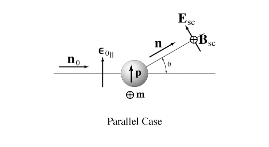
Figure 9-6-5d1 shows the scattering geometry for parallel polarization (incident light polarized in the scattering plane). The induced dipoles are denoted by p (electric) and m (magnetic). See also next figure.
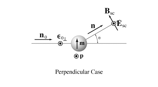
Figure 9-6-5d2 is analogous to the above for perpendicular polarization (incident light polarized in the scattering plane). The text refers to these two figures in paragraphs 9-6-3a and 9-6-5d.
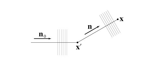
Figure 9-6-7b shows the meanings of x (field point) and x' (source point) in the scattering process.
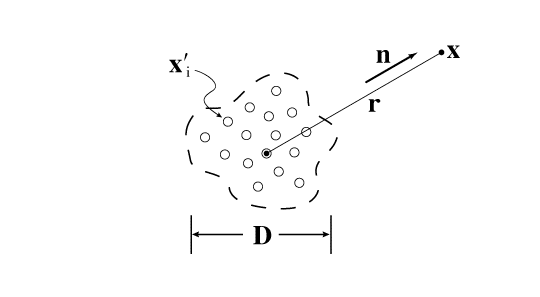
Figure 9-6-8b shows the scattering geometry for scatterers assembled in a region of typical dimension D. The field point is denoted by x and the positions of the scatterers by xi.
Figures drawn by Bill McHargue.