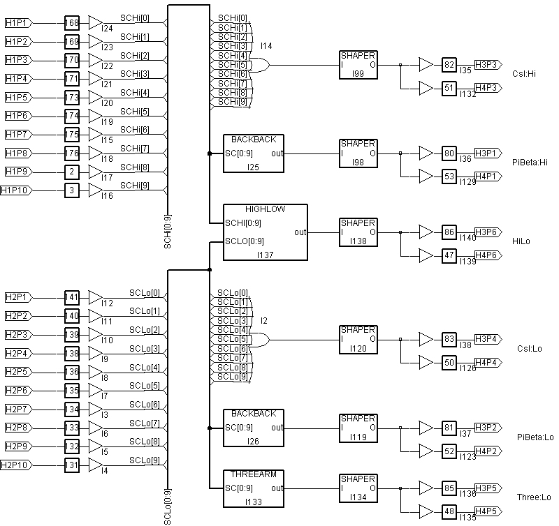
The labels on the inputs and outputs are in the form HnPm, where n is the header number (1...4 from top to down) and m is the pin number (1..16, as labeled on the unit).
Here is the toplevel schematic:
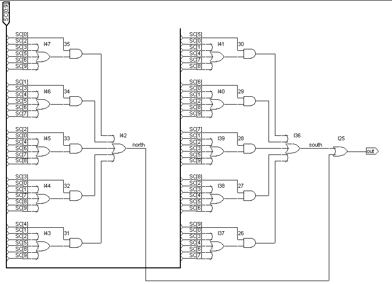
It contains the back-to-back logic:
Here are the shapers:

The additional buffers at the output of the shapers are for signal delay.