Waves in Two and Three Dimensions
Michael Fowler, University of Virginia
Introduction
So far, we’ve looked at waves in one dimension, traveling along a string or sound waves going down a narrow tube. But waves in higher dimensions than one are very familiarwater waves on the surface of a pond, or sound waves moving out from a source in three dimensions.
It is pleasant to find that these waves in higher dimensions satisfy wave equations which are a very natural extension of the one we found for a string, andvery importantthey also satisfy the Principle of Superposition, in other words, if waves meet, you just add the contribution from each wave. In the next two paragraphs, we go into more detail, but this Principle of Superposition is the crucial lesson.
The Wave Equation and Superposition in One Dimension
For waves on a string, we found Newton’s laws applied to one bit of string gave a differential wave equation,
and it turned out that sound waves in a tube satisfied the same equation. Before going to higher dimensions, I just want to focus on one crucial feature of this wave equation: it’s linear, which just means that if you find two different solutions and then is also a solution, as we proved earlier.
This important property is easy to interpret visually: if you can draw two wave solutions, then at each point on the string simply add the displacement of one wave to the other you just add the waves togetherthis also is a solution. So, for example, as two traveling waves moving along the string in opposite directions meet each other, the displacement of the string at any point at any instant is just the sum of the displacements it would have had from the two waves singly. This simple addition of the displacements is termed “interference”, doubtless because if the waves meeting have displacement in opposite directions, the string will be displaced less than by a single wave. It’s also called the Principle of Superposition.
The Wave Equation and Superposition in More Dimensions
What happens in higher dimensions? Let’s consider two dimensions, for example waves in an elastic sheet like a drumhead. If the rest position for the elastic sheet is the plane, so when it’s vibrating it’s moving up and down in the -direction, its configuration at any instant of time is a function
In fact, we could do the same thing we did for the string, looking at the total forces on a little bit and applying Newton’s Second Law. In this case that would mean taking one little bit of the drumhead, and instead of a small stretch of string with tension pulling the two ends, we would have a small square of the elastic sheet, with tension pulling all around the edge. Remember that the net force on the bit of string came about because the string was curving around, so the tensions at the opposite ends tugged in slightly different directions, and didn’t cancel. The term measured that curvature, the rate of change of slope. In two dimensions, thinking of a small square of the elastic sheet, things are more complicated. Visualize the bit of sheet to be momentarily like a tiny patch on a balloon, you’ll see it curves in two directions, and tension forces must be tugging all around the edges. The total force on the little square comes about because the tension forces on opposite sides are out of line if the surface is curving around, now we have to add two sets of almost-opposite forces from the two pairs of sides. I’m not going to go through all the math here, but I hope it’s at least plausible that the equation is:
The physics of this equation is that the acceleration of a tiny bit of the sheet comes from out-of-balance tensions caused by the sheet curving around in both the - and -directions, this is why there are the two terms on the left hand side.
Remarkably, this same equation comes out for sound waves and for the electromagnetic waves we now know as radio, microwaves, light, X-rays: so it’s called the Wave Equation.
And, going to three dimensions is easy: add one more term to give
This sum of partial differentiations is so common in physics that there’s a shorthand:
Just as we found in one dimension traveling harmonic waves with you can verify that the three-dimensional equation has harmonic solutions
and now
, where
In fact, is a vector in the direction the wave is moving. The electric and magnetic fields in a radio wave or light wave have just this form (or, closer to the source, a very similar equivalent expression for outgoing spheres of waves, rather than plane waves).
It’s important to realize that this more complicated equation is still a linear equationthe principle of superposition still holds. If two waves on an elastic sheet, or the surface of a pond, meet each other, the result at any point is given by simply adding the displacements from the individual waves. (Assuming as always small waves, so the water waves don’t fall apart into foam.)
We’ll begin by thinking about waves propagating freely in two and three dimensions, than later consider waves in restricted areas, such as a drum head.
How Does a Wave Propagate in Two and Three Dimensions?
A one-dimensional wave doesn’t have a choice: it just moves along the line (well, it could get partly reflected by some change in the line and part of it go backwards). But when we go to higher dimensions, how a wave disturbance starting in some localized region spreads out is far from obvious. But we can begin by recalling some simple cases: dropping a pebble into still water causes an outward moving circle of ripples. If we grant that light is a wave, we notice a beam of light changes direction on going from air into glass. Of course, it’s not immediately evident that light is a wave: we’ll talk a lot more about that later.
Huygen’s Picture of Wave Propagation
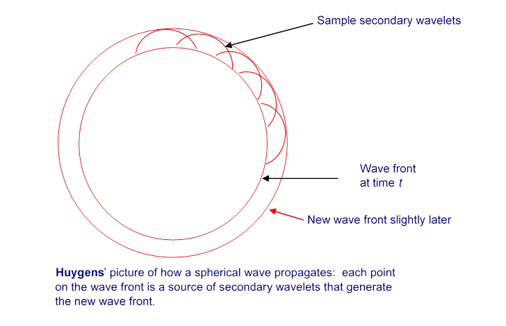
If a point source of light is switched on, the wavefront is an expanding sphere centered at the source. Huygens suggested that this could be understood if at any instant in time each point on the wavefront was regarded as a source of secondary wavelets, and the new wavefront a moment later was to be regarded as built up from the sum of these wavelets. For a light shining continuously, this process just keeps repeating.
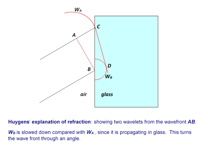
What use is this idea? For one thing, it explains refractionthe change in direction of a wavefront on entering a different medium, such as a ray of light going from air into glass.
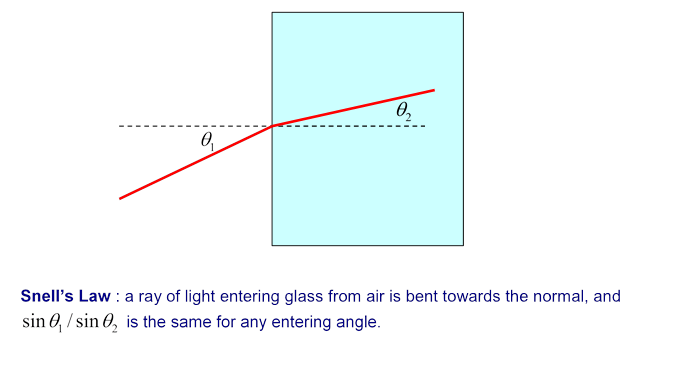
If the light moves more slowly in the glass, velocity v instead of c, with v < c, then Huygen’s picture explains Snell’s Law, that the ratio of the sines of the angles to the normal of incident and transmitted beams is constant, and in fact is the ratio c/v.
This is evident from the diagram below: in the time the wavelet centered at A has propagated to C, that from B has reached D, the ratio of lengths AC/BD being c/v. But the angles in Snell’s Law are in fact the angles ABC, BCD, and those right-angled triangles have a common hypotenuse BC, from which the Law follows.
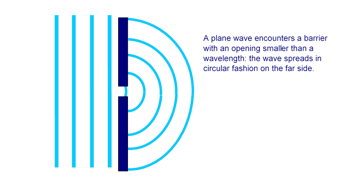
Huygens’ picture also provides a ready explanation of what happens when a plane wave front encounters a barrier with one narrow opening: and by narrow, we mean small compared with the wavelength of the wave. It’s easy to arrange this for water waves: it’s found that on the other side of the barrier, the waves spread out in circular fashion form the small hole.
Two-Slit Interference: How Young measured the Wavelength of Light
If the slit is wider than a wavelength or so, the pattern gets more complicated, as we would expect from Huygens’ ideas, because now the waves on the far side arise from a line of sources, not what amounts to one point. To investigate this further, consider the simplest possible next case: a barrier with two small holes in it, so on the far side we’re looking at waves radiating outwards from, effectively, two point sources.
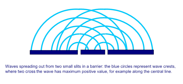
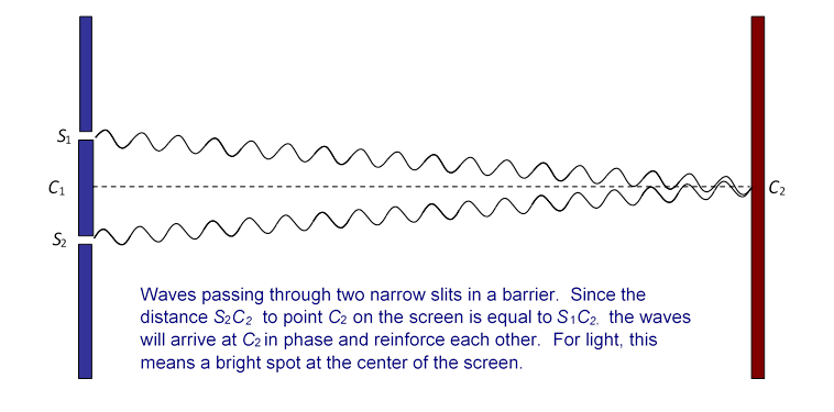
For two synchronized sources generating harmonic waves, at any point in the tank equally distant from the two sources (the central line in the picture above), the waves will add, the water will be maximally disturbed. For light waves, there will be a maximum in brightness at the center of a screen as shown in the diagram:
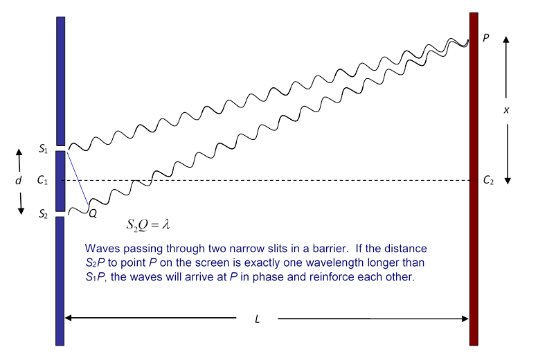
For light waves passing through two narrow slits and shining on a screen (on the right) there will be another bright spot at a point P away from the center C2 of the screen, provided the distances of P from the two slits differ by a whole number of wavelengths:
On the other hand, at a point approximately half way from the center of the screen to P the waves from the two sources will arrive at the screen exactly out of phase: the crest of one will arrive with the trough of the other, they will cancel, and there will be no light. Evidently, then, we will see on the screen a series of bright areas and dark areas, the brightest spots being at the points where the waves from the two slits arrive exactly in phase.
There is an animation of this pattern formation here.
This pattern, generated by what is called interference
between the waves, and also referred to as a diffraction pattern is
historically important, because it was used to establish that light is a wave,
by Thomas Young in 1807. (Recall
Young used the pattern to find the wavelengths of red and violet light. His method can be understood from the diagram above. We did the experiment in class with a slit separation of about 0.2 mm., giving bright spots on the screen about 3 cm apart, with a screen 10 m from the slits.
That is to say, in the diagram above we had and we found (within a percent or two). Looking at the diagram, it’s clear that the angle to P from the slits is very small, in fact it’s So the diagram as drawn is very exaggerated!
Now, the line S1Q is perpendicular to the light rays setting off for P (they are extremely close to parallel). The angle between S1Q and S1S2 is the same as that between C1P and C1C2, that is, This means that the lengths S1Q and S1S2 are effectively equal, and therefore that
This is very accurate for such a small angle, and for the data as given here the wavelength of the light
Another Bright Spot
About ten years after Young’s result a French civil engineer, Augustin Fresnel, independently developed a wave theory of light, and gave a more complete mathematical analysis. This was disputed by the famous French mathematician Simeon Poisson, who pointed out that if the wave theory were true, one could prove mathematically that in the sharp shadow of a small round object, there would be a bright spot in the center, because the waves coming around the circumference all around would add there. This seemed ridiculousbut French physicist Francois Arago actually did the experiment, and found the spot! The wave theory of light had arrived.