When using a polarized target, the holding field deflects all charged particles
entering and exiting the target. For the ![]() case of interest, the holding field is in the scattering plane, in the direction
perpendicular to
case of interest, the holding field is in the scattering plane, in the direction
perpendicular to
![]() . The field has a component perpendicular to both the incident and
scattered electron directions and results in small, yet significant deflections.
This deflection of the electrons
is minimized by performing the experiment at the highest incident energy (which
corresponds
to the smallest angle) possible. This at the same time yields the greatest the
figure of merit
for a fixed luminosity. For the energies and angles listed in Table 1 the
maximum deflection for the incident electron in traversing a target field of 1.34
T-m is 4.3
. The field has a component perpendicular to both the incident and
scattered electron directions and results in small, yet significant deflections.
This deflection of the electrons
is minimized by performing the experiment at the highest incident energy (which
corresponds
to the smallest angle) possible. This at the same time yields the greatest the
figure of merit
for a fixed luminosity. For the energies and angles listed in Table 1 the
maximum deflection for the incident electron in traversing a target field of 1.34
T-m is 4.3 ![]() . For the scattered electron the maximum deflection is less
than 3.3
. For the scattered electron the maximum deflection is less
than 3.3 ![]() .
.
Unless compensated for the deflection of the incident and final electrons can be
troublesome. When the beam is deflected down, the scattering plane is tilted such
that ![]() points toward the floor. The angular direction of
points toward the floor. The angular direction of ![]() relative
to the laboratory floor,
relative
to the laboratory floor, ![]() , is given
by
, is given
by
![]()
where ![]() is the beam deflection angle. At high energies
and small angles a small incident beam deflection is magnified, resulting in a large
deflection of
is the beam deflection angle. At high energies
and small angles a small incident beam deflection is magnified, resulting in a large
deflection of ![]() . For example, at Q
. For example, at Q ![]() ,
, ![]() and
and
![]() . Since the scattered electron is deflected vertically as
well, the scattering plane has a significant tilt with respect to the floor. To
detect the neutron along
. Since the scattered electron is deflected vertically as
well, the scattering plane has a significant tilt with respect to the floor. To
detect the neutron along ![]() at a
at a ![]() = 2, the neutron detector at 8
meters from the target would be 1 meter below the horizontal. Further complications
arise since the angle of the spectrometer,
= 2, the neutron detector at 8
meters from the target would be 1 meter below the horizontal. Further complications
arise since the angle of the spectrometer, ![]() is different from the true
scattering angle when the beam is deflected. This difference between
is different from the true
scattering angle when the beam is deflected. This difference between ![]() and
and
![]() is greatest in the forward direction.
is greatest in the forward direction.
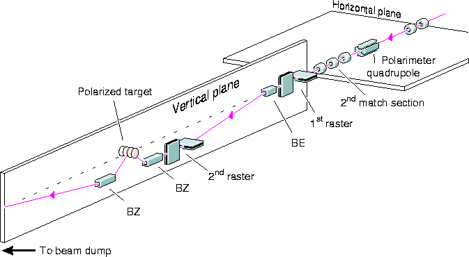
CEBAF has designed a chicane[22] in coordination with this collaboration in order to compensate for the effects of the target field. This chicane is designed such as to obtain a horizontal incident beam at the center of the polarized target. The gap of the magnet will be large enough (2.5cm and 3.8cm for BE and BZ, respectively) to allow for rastering of the beam. The width of the poles is such that the chicane can be used over a large range of incident energies; also, very small deflections (where the chicane magnets can be used to correct the alignment of the incident beam) are possible without mechanical rearrangement of the chicane. The upstream chicane magnets will be part of the initial complement of equipment in Hall C. The downstream chicane will direct the incident beam towards the beam dump.
The chicane is shown schematically in Figure 7. The magnets contracts have been awarded and the magnets should be delivered by September 1993.

Figure 7: The Hall C chicane. Also indicated is the beam rastering system which will
be available when Hall C is ready for beam. Not shown are
the beam position monitors and beam current monitors.