Heat Engines: the Carnot Cycle
Applet here!
Michael Fowler
The Ultimate in Fuel Efficiency for a Heat Engine
All standard heat engines (steam, gasoline, diesel) work by supplying heat to a gas, the gas then expands in a cylinder and pushes a piston to do its work. So it’s easy to see how to turn heat into work, but that’s a one shot deal. We need it to keep repeating to have a useful engine. The heat and/or the gas must therefore be dumped out of the cylinder before the next cycle begins, otherwise all the work the gas delivered on expanding will be used up compressing it back!
Our aim in this lecture is to figure out just how efficient such a heat engine can be: what’s the most work we can possibly get for a given amount of fuel in a cyclical process? We’ll examine here the model stripped to its essentials: an ideal gas is enclosed in a cylinder, with external thermal connections to supply and take away heat, and a frictionless piston for the gas to perform (and if necessary absorb) mechanical work:
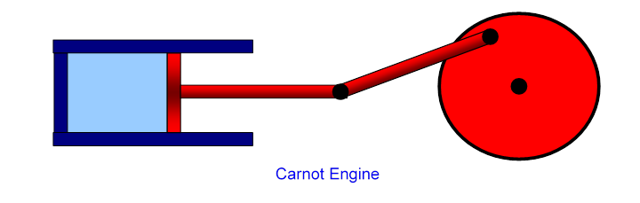
This simplest heat engine is called the Carnot engine, for which one complete heating/cooling, expanding/contracting cycle back to the original gas volume and temperature is a Carnot cycle, named after Sadi Carnot who in 1820 derived the correct formula for the maximum possible efficiency of such a heat engine in terms of the maximum and minimum gas temperatures during the cycle.
Carnot's result was that if the maximum hot temperature reached by the gas is and the coldest temperature during the cycle is (degrees kelvin, or rather just kelvin, of course) the fraction of heat energy input that comes out as mechanical work , called the efficiency, is
Efficiency =
This was an amazing result, because it was exactly correct, despite being based on a complete misunderstanding of the nature of heat!
How Understanding Waterwheel Efficiency was the Key to Understanding the Heat Engine
Carnot believed that heat, like electricity, was a fluid that flowed from hot things to cold things (and somehow through space as radiation).
What motivated Carnot to attempt to calculate steam energy efficiency in 1820? Well, it was the time of the Industrial Revolution, and the efficiency of your power supply determined your profit margin.
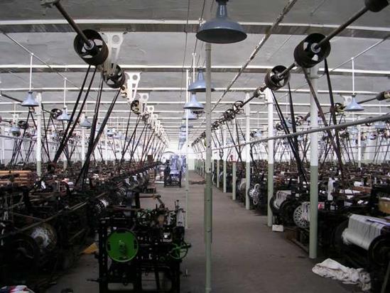 Big engines
were primarily used in mass production of cloth, in factories called mills. Up
to the late 1700's these mills were located by fast flowing rivers, the power
source was a large waterwheel, it turned a long rotating rod that stretched the
length of the factory. Ropes took power
from pulleys on this rod to turn individual looms, which were operated by
semiskilled laborers, often children. The picture here is much later (1914),
and steam-driven, but shows the powering
scheme.
Big engines
were primarily used in mass production of cloth, in factories called mills. Up
to the late 1700's these mills were located by fast flowing rivers, the power
source was a large waterwheel, it turned a long rotating rod that stretched the
length of the factory. Ropes took power
from pulleys on this rod to turn individual looms, which were operated by
semiskilled laborers, often children. The picture here is much later (1914),
and steam-driven, but shows the powering
scheme.
The steam engine offered an attractive alternative: it didn't need to be close to a river. But it needed coal or wood for fuel, unlike the watermill.
Since the main source of industrial power up to the late 1700's was the waterwheel, a lot of thought went into making it as efficient as possible, and since Carnot thought heat was a fluid, he used waterwheel thinking in analyzing the steam engine. So, how do you make a waterwheel as efficient as possible?
The water loses potential energy as it is carried down by the wheel, so the most energy possible is watts, where is the mass of water flowing per second. (We're ignoring possible kinetic energy contributions from the ingoing water coming in fastthis is a very small effect, and doesn't apply to Carnot's heat engine analysis.)
How is energy wasted? Obviously, we need as little friction in the wheel as possible. There must be smooth flow: no water splashing around.
The water must flow into and off the wheel without dropping any significant height, or it loses that much potential energy without producing work.
A perfect water wheel would be reversible: it could be used to drive a copy of itself backwards, to lift up the same amount of water per second that fell.
Aside : A Modern Water Wheel in Virginia
There is in Virginia a pretty efficient water wheel: it’s about 80% efficientthe Bath County hydroelectric pumped storage station. This is a water wheel, actually a turbine, but that amounts to the same thing better designed, that works both ways. Water from an upper lake falls through a pipe to a turbine and the lower lake, generating electrical power. Alternatively, electric power can be supplied to pump the water back up. Why bother? Because demand for electricity varies, and it’s better to avoid if possible building power stations that are only running during peak demand. It’s cheaper to store power at times of low demand.
The drop h is about 1200 feet, 380 meters. The flow rate is about a thousand tons a second. The plant generates about 3 Gigawatts, substantially more than a two-unit nuclear plant, such as North Anna.
Carnot’s Idea: a “Water Wheel” for Heat
Carnot's belief that heat was a fluid (we still picture it flowing that way in thinking of heat conduction, or, say, cooking) led him to analyze the steam engine in parallel to a water wheel. In the water wheel, the water falls through a gravitational potential difference and that potential energy is transformed into work by the wheel. The "electric fluid" we now see as a fluid losing electrical potential energy and producing work or heat. So, what about the heat "caloric fluid" (as it was called)? Obviously, the analogy to gravitational potential is just temperature! As the gas in the cylinder expands, it does work, but its temperature goes down.
Carnot assumed that the steam engine was nothing but a water wheel for this caloric fluid, so the most efficient engine would have minimal friction, but also, in analogy with the water entering and leaving the wheel gently with no intermediate loss of height, the heat would enter and leave the gas in the engine isothermally (remember the temperature is analogous to the gravitational potential, thus the height). Therefore, by analogy with the drop in temperature measures the potential energy given up by a unit amount of the “heat fluid”.
The most efficient steam engine would have isothermal heat exchange (negligible temperature differences in heat exchange), like the most efficient water wheel (only a tiny drop as the water enters and leaves the wheel). Of course, this is the theoretical limit: some drop is necessary for operation. But the important point is that in the limit of perfect efficiency, both engine and waterwheel are reversibleif supplied with work, they could transform it into the same amount of heat they would need to generate that work in the first place.
But how does that relate to the energy expended producing the heat in the first place? Well, Carnot knew something else: there was an absolute zero of temperature. Therefore, he reasoned, if you cooled the fluid down to absolute zero, it would give up all its heat energy. So, the maximum possible amount of energy you can extract by cooling it from to is, what fraction is that of cooling it to absolute zero?
It’s just
Of course, the caloric fluid picture isn’t right, but this result is! This is the maximum efficiency of a perfect engine: and remember, this engine is reversible. We'll see how to use that important fact later.
Getting Work Out of a Hot Gas Efficiently: Isothermal and Adiabatic Flows
Now let’s turn to the details of getting the most work out of a heated gas. We want the process to be as close to reversible as possible: there are two ways to move the piston reversibly: isothermally, meaning heat gradually flows in or out, from a reservoir at a temperature infinitesimally different from that of the gas in the piston, and adiabatically, in which there is no heat exchange at all, the gas just acts like a spring.
So, as the heat is supplied and the gas expands, the temperature of the gas must stay the same as that of the heat supply (the “heat reservoir”): the gas is expanding isothermally. Similarly, it must contract isothermally later in the cycle as it sheds heat.
To figure out the efficiency, we need to track the engine through a complete cycle, finding out how much work it does, how much heat is taken in from the fuel, and how much heat is dumped in getting ready for the next cycle. You might want to look at the applet to get the picture at this point: the cycle has four steps, an isothermal expansion as heat is absorbed, followed by an adiabatic expansion, then an isothermal contraction as heat is shed, finally an adiabatic contraction to the original configuration. We’ll take it one step at a time.
Step 1: Isothermal Expansion
So the first question is: How much heat is supplied, and how much work is done, as the gas expands isothermally? Taking the temperature of the heat reservoir to be ( for hot), the expanding gas follows the isothermal path in the plane.
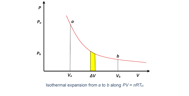
The work done by the gas in a small volume expansion is just the area under the curve (as we proved in the last lecture).
Hence the work done in expanding isothermally from volume to is the total area under the curve between those values,
There is no change in its internal energy during this expansion, so the total heat supplied must be the same as the external work the gas has done.
In fact, this isothermal expansion is only the first step: the gas is at the temperature of the heat reservoir, hotter than its other surroundings, and will be able to continue expanding even if the heat supply is cut off. To ensure that this further expansion is also reversible, the gas must not be losing heat to the surroundings. That is, after the heat supply is cut off, there must be no further heat exchange with the surroundings, the expansion must be adiabatic.
Step 2: Adiabatic Expansion
By definition, no heat is supplied in adiabatic expansion, but work is done.
The work the gas does in adiabatic expansion is like that of a compressed spring expanding against a forceequal to the work needed to compress it in the first place, for an ideal (and perfectly insulated) gas. So adiabatic expansion is reversible.
In adiabatic expansion, the pressure falls off more steeply as the volume increases, because, in contrast to the isothermal case, no heat energy is being supplied to the gas as it expands, so the work the piston can do in an incremental expansion is necessarily less, the pressure must be lower.
Of course, Carnot didn't see it this way, but it's helpful to think of the gas in terms of molecules flying around, and the pressure from them bouncing off the piston. Look at the applet here to see how expanding the volume without supplying thermal energy lowers the pressure. For isothermal compression or expansion, the bouncing ball's speed would stay constant (energy exchanged with thermal vibrations in the walls as it bounced off).
The internal energy of moles of an ideal gas at temperature is This is (in our modern picture) the kinetic energy of the molecules, and does not depend on the volume occupied by the gas. Therefore, the change in internal energy in adiabatic expansion is
so this is the work done by the gas expanding against the external pressure.
Steps 3 and 4: Completing the Cycle
We’ve looked in detail at the work a gas does in expanding as heat is supplied (isothermally) and when there is no heat exchange (adiabatically). These are the two initial steps in a heat engine, but it is necessary for the engine to get back to where it began, for the next cycle. The general idea is that the piston drives a wheel (as in the diagram at the beginning of this lecture), which continues to turn and pushes the gas back to the original volume.
But it is also essential for the gas to be as cold as possible on this return leg, because the wheel is now having to expend work on the gas, and we want that to be as little work as possibleit’s costing us. The colder the gas, the less pressure the wheel is pushing against.
To ensure that the engine is as efficient as possible, this return path to the starting point must also be reversible. We can’t just retrace the path taken in the first two legs, that would take all the work the engine did along those legs, and leave us with no net output. Now the gas cooled during the adiabatic expansion from b to c, from to say, so we can go some distance back along the reversible colder isotherm Obviously, that can't get us all the way back to because that’s at the hotter temperature It's equally clear, though, that our best bet is to stay as cold as possible for as long as possible, provided we can get back to the start on a reversible path (otherwise we're losing efficiency). There's really only one option: we stay on the cold isotherm until we meet the adiabat that passes through the original point, then complete the cycle by going up that adiabat (remember the adiabats are steeper than the isotherms).
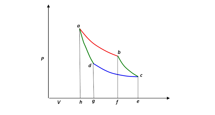
To picture the Carnot cycle in the (P, V) plane, recall from the previous lecture the graph showing two isotherms and two adiabats:
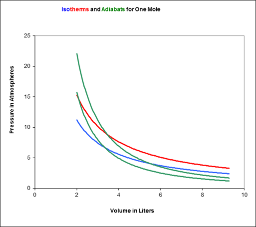
Carnot’s cycle is around that curved quadrilateral having these four curves as its sides.
Let us redraw this, slightly less realistically but more conveniently:
Efficiency of the Carnot Engine
In a complete cycle of Carnot’s heat engine, the gas traces the path abcd. The important question is: what fraction of the heat supplied from the hot reservoir (along the red top isotherm), let’s call it is turned into mechanical work? This fraction is of course the efficiency of the engine.
Since the internal energy of the gas is the same at the end of the cycle as it was at the beginning—it’s back to the same and it must be that the work done equals the net heat supplied,
being the heat dumped as the gas is compressed along the cold isotherm.
The efficiency is the fraction of the heat input that is actually converted to work, so
This is the answer, but it’s not particularly useful: measuring heat flow, especially the waste heat, is quite difficult. In fact, it was long believed that the heat flow out was equal to that flowing in, and this seemed quite plausible because the efficiency of early engines was very low.
But there’s a better way to express this.
Now the heat supplied along the initial hot isothermal path ab is equal to the work done along that leg, (from the paragraph above on isothermal expansion):
and the heat dumped into the cold reservoir along cd is
looks complicated, but actually it isn’t!
The expression can be greatly simplified using the adiabatic equations for the other two sides of the cycle:
Dividing the first of these equations by the second,
and using that in the preceding equation for
So for the Carnot cycle the ratio of heat supplied to heat dumped is just the ratio of the absolute temperatures!
Remember this: it’ll be important in developing the concept of entropy.
The work done can now be written simply:
Therefore the efficiency of the engine, defined as the fraction of the ingoing heat energy that is converted to available work, is
These temperatures are of course in degrees Kelvin, so for example the efficiency of a Carnot engine having a hot reservoir of boiling water and a cold reservoir ice cold water will be , just over a quarter of the heat energy is transformed into useful work. This is the very same expression Carnot found from his water wheel analogy.
After all the effort to construct an efficient heat engine, making it reversible to eliminate “friction” losses, etc., it is perhaps somewhat disappointing to find this figure of 27% efficiency when operating between 0℃ and 100℃. In fact, when in the early 1800's the first steam locomotives were designed, it was found that the power/weight ratio needed to move along a track could only be achieved by having high pressure boilers, meaning boiling water at a few atmospheres (up to ten of so) pressure. At 6 atmospheres pressure, for example, the boiling temperature is about 280℃, or say 550K (kelvin), so operating between that and room temperature at 300K gives a theoretical efficiency of about 250/550, or 45%, a big improvement.